
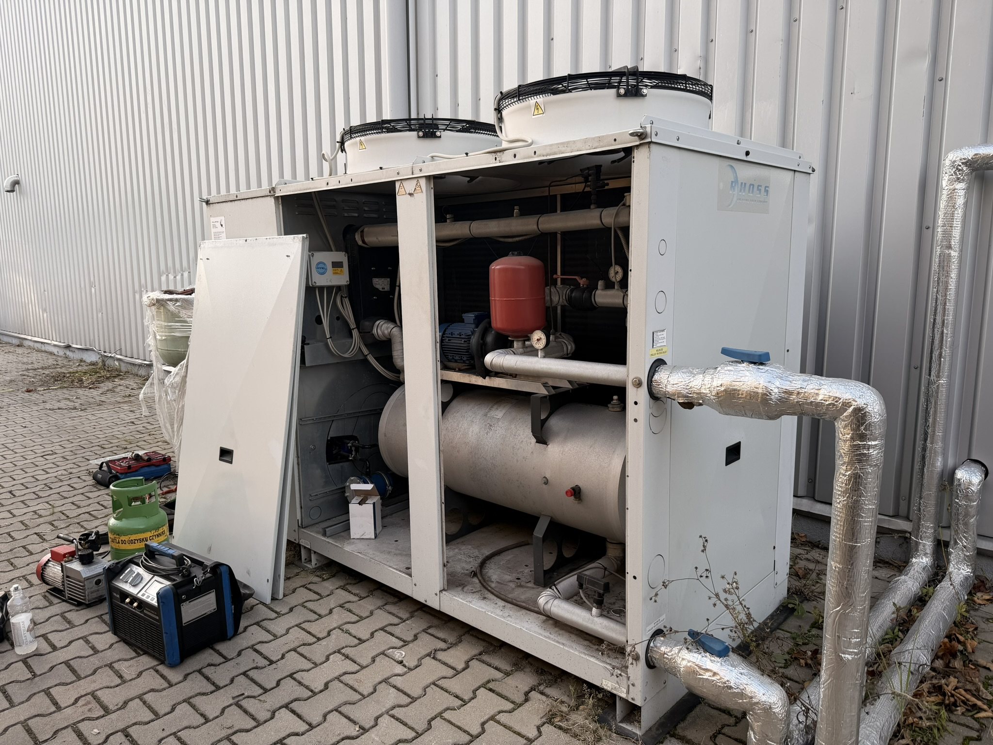
A chilled water system distributes cooling from one or more chillers to air handling units, fan coils or process machines through a closed pipe circuit. Stable operation depends on correct temperatures, sufficient flow, enough water volume and proper frost protection.
When a chiller trips repeatedly, the cause is often not in the chiller at all but in the water circuit around it. This guide covers the hydraulic side of the system: the parameters we measure, the typical design values and the faults we find most often during service visits.
Main components of a chilled water system
- Chiller with its evaporator, the source of cooling.
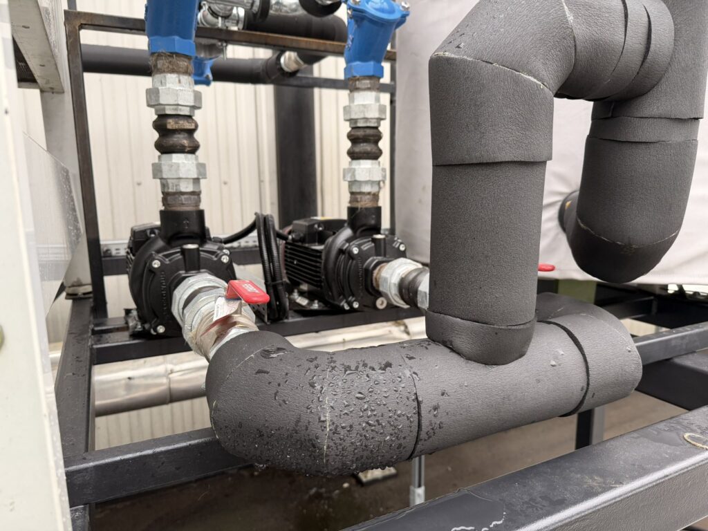
- Circulation pumps, often with a standby pump and, in newer systems, frequency inverters.
- Buffer tank, which adds water volume and stabilises the control.
- Expansion vessel and safety valve, which absorb thermal expansion and protect the circuit.
- Strainers and filters, which protect the evaporator and the pumps.
- Consumers: cooling coils in air handling units, fan coils, plate heat exchangers or machine cooling circuits.
- Valves: balancing valves, two or three-way control valves, isolation valves and air vents.
Supply and return temperatures
The design temperature pair defines how much water must flow for a given cooling load. Comfort cooling commonly uses 7/12 °C, while modern systems designed for higher efficiency or for chilled beams and radiant ceilings use 10/15 °C, 14/18 °C or even 16/19 °C. Process cooling depends on the machine: injection moulding tools, printing presses, lasers and hydraulic oil coolers all have their own requirements.
The temperature difference between return and supply, the delta T, is one of the most informative values in the system. A design delta T of 5 K that has fallen to 2 K means either that the load is low or, more often, that too much water is bypassing the consumers. Low delta T forces the chiller to cycle and the pumps to move more water than needed.
Flow rate and pressure drop
The flow rate follows directly from the cooling load and the delta T. For water, the flow in cubic metres per hour is approximately the cooling capacity in kW multiplied by 0.86 and divided by the delta T. The table shows typical values for a 5 K difference.
| Cooling capacity | Water flow at delta T 5 K | Water flow at delta T 3 K |
|---|---|---|
| 50 kW | about 8.6 m³/h | about 14.3 m³/h |
| 100 kW | about 17.2 m³/h | about 28.7 m³/h |
| 250 kW | about 43 m³/h | about 72 m³/h |
| 500 kW | about 86 m³/h | about 143 m³/h |
Glycol mixtures have a lower specific heat and higher viscosity, so for the same capacity a slightly higher flow is needed and the pressure drop increases. The cooling capacity calculator takes this into account.
On site, the flow through the evaporator is best checked by measuring the pressure drop across it and comparing it with the manufacturer curve. A pressure drop below the expected value means low flow, which can be caused by a blocked strainer, an air lock, a worn pump impeller or a partly closed valve. Most chillers have a flow switch or a differential pressure switch that stops the unit when the flow falls below a safe limit. A flow alarm should never be bridged: low flow is the most common cause of evaporator freeze damage.
Pipe velocity
Typical design velocities are 0.5 to 1.0 m/s in small pipes and 1.0 to 2.0 m/s in main pipes. Higher velocities cause noise and erosion, lower ones allow air and sediment to collect. Sizing rules are covered on our page about chilled water pipe sizing.
Buffer tanks and water volume
A chiller compressor should not start more often than the manufacturer allows, typically 6 to 12 starts per hour depending on compressor type and size. If the system holds too little water, the chilled water temperature falls through the control band within a minute or two, the compressor stops, and a short time later it starts again. This short cycling overheats motor windings, causes oil return problems and wears contactors.
Manufacturers usually state a minimum water volume per kW of cooling capacity. Values of 3 to 5 litres per kW are common for comfort applications with several compressor stages, while process applications with tight temperature tolerance and a single compressor often need 6 to 10 litres per kW or more. When the pipework and consumers do not provide this volume, a buffer tank is installed, usually in the return line so that it also evens out temperature peaks from the process.
Glycol and frost protection
Any part of the circuit that can be exposed to temperatures below 0 °C needs protection. This applies to outdoor chillers and pipes, dry coolers, free cooling coils and systems that operate with supply temperatures below about 4 °C. Options are a water and glycol mixture, trace heating on exposed sections, or a hydraulic layout with a heat exchanger that keeps glycol only in the outdoor part.
The glycol concentration should be chosen for the lowest expected temperature with a margin, and it must be checked regularly, because top-ups with plain water dilute it over time. Inhibitors also wear out, so a mixture with the correct freezing point can still be corrosive. More information is in our guide to antifreeze fluids.
Typical faults on the water side
- Air in the circuit after refilling, causing noise, unstable flow and flow alarms.
- Clogged strainers after works on the installation or due to corrosion products.
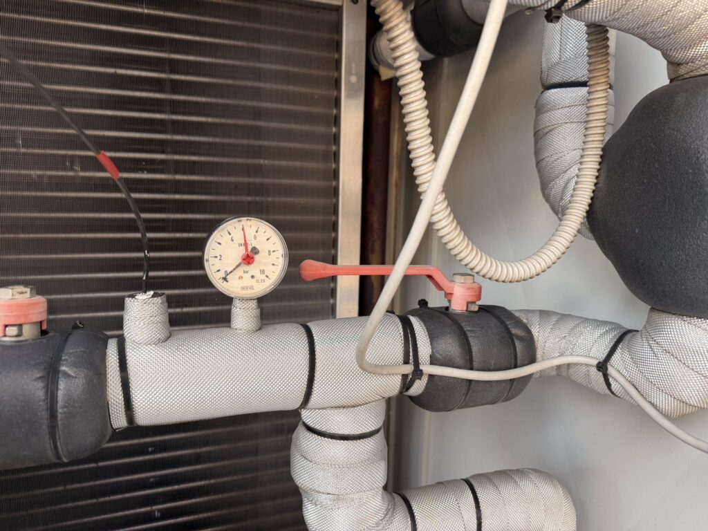
- Loss of pressure because of a defective expansion vessel or small leaks at valves and pump seals.
- Control valves stuck open, causing low delta T and wasted pump energy.
- Condensation on poorly insulated pipes when the supply temperature is below the dew point of the surrounding air.
- Sludge and magnetite in old steel systems that were filled with untreated water.
What we measure during a visit
A water side check takes little time and often explains chiller alarms that seemed random. We record supply and return temperatures at the chiller and at selected consumers, the evaporator pressure drop, static and dynamic system pressure, pump currents and, where relevant, glycol concentration. The results go into the report together with the refrigerant side readings, so the maintenance team gets one consistent picture of the system.
Frequently asked questions
What is a normal pressure in a chilled water system?
There is no single value: the static pressure depends on the height of the building. A common rule is to keep the pressure at the highest point at least 0.5 to 1 bar above atmospheric. The important thing is that the cold fill pressure stays stable over time.
Why does the chiller show a flow alarm after the system was refilled?
Most often air is trapped in the pump or at high points of the circuit. Venting at all high points and at the pump, and cleaning the strainer, solves the majority of these cases.
Do I need a buffer tank?
Only if the water volume in the system is below the manufacturer minimum for your chiller. The volume of pipes and consumers can be estimated from the drawings; our buffer tank calculator gives a first estimate.
How often should the chilled water be tested?
For glycol systems we recommend at least once a year, before winter. Pure water systems with signs of corrosion or sludge should also be tested, including pH and the appearance of a sample.
Can I raise the chilled water setpoint to save energy?
Often yes, if the air handling units or the process can still remove the required heat and humidity. Each kelvin higher typically saves a few percent of chiller energy. Test the change in steps and watch room or process conditions.
Chiller trips without an obvious reason?
We check the refrigerant circuit and the water side in one visit and explain the cause in the report.