
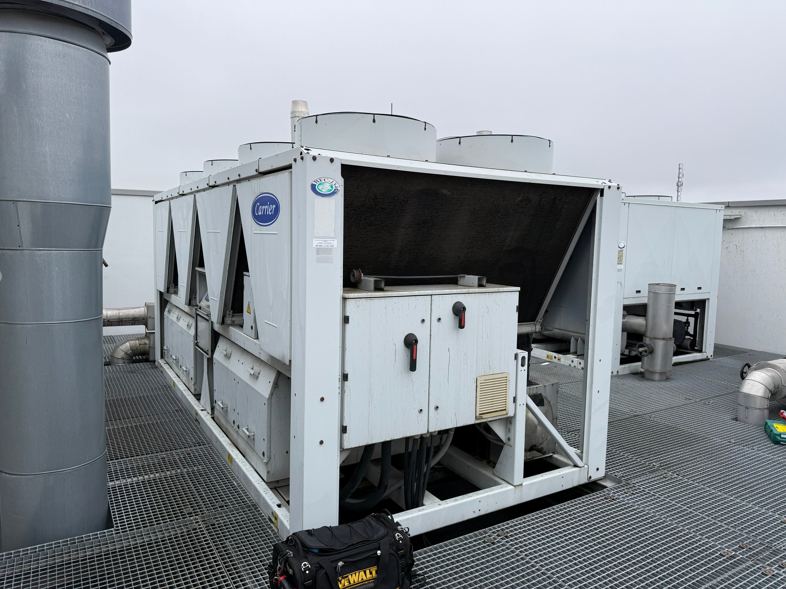
Estimate the minimum water volume a chiller needs to avoid short cycling and the size of the buffer tank, from the capacity steps, the allowed starts per hour and the control band.
Minimum water volume and buffer tank size
Smallest step: 100 for one on/off compressor, 50 for two equal compressors, 25 for four, or the minimum load of an inverter compressor. Always compare with the minimum volume in the chiller manual.
Why a chiller needs a minimum water volume
A compressor must not start too often. Each start draws a high current, heats the motor windings and, in the first seconds, runs with poor oil supply. Manufacturers therefore limit starts, typically to 6 to 12 per hour, and require a minimum running time. If the water volume in the circuit is small, the water cools down within a minute after the compressor starts, the controller stops it, the water warms up just as fast and the cycle repeats. The result is short cycling, unstable supply temperature and early compressor failure.
The water in the pipes, the evaporator and the consumers acts as a thermal store. When that volume is too small, a buffer tank adds the missing volume.
The formula
The worst case for cycling is a load equal to half of the smallest capacity step. The compressor then runs and stands still for equal times. If the controller allows N starts per hour and switches over a control band dT, the minimum volume is:
V = Q_step x 3600 / (4 x N x rho x cp x dT)
Q_step is the smallest capacity step in kW, rho x cp the volumetric heat capacity of the fluid in kJ/(m³ K) and V the result in m³. The factor 4 comes from the cycle analysis: at half load the water warms up and cools down over the control band once per cycle, in a period of 3600/N seconds.
Example: a 100 kW chiller with two equal compressors, 6 starts per hour, a 3 K control band and water gives 50 x 3600 / (4 x 6 x 4,190 x 3) = 0.60 m³, so about 600 litres or 6 l/kW. If the pipes, the evaporator and the coils already hold 200 litres, the buffer tank needs 400 litres.
Assumptions and limits
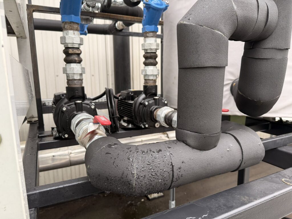
- All of the system water takes part in the storage. A tank with poor connections, where the flow bypasses most of the volume, stores less than its size suggests.
- The control band is the temperature span between compressor start and stop. Controllers with a narrow band or fast reacting control on leaving water need more volume.
- Inverter compressors need much less volume, because they modulate down before they stop. Enter their minimum load as the smallest step.
- Minimum running times or anti-recycle timers set by the manufacturer are not part of the formula; the manual has the final word.
Typical values
| Application | Typical minimum volume |
|---|---|
| Comfort cooling, several compressors or inverter | 3 to 5 l/kW |
| Comfort cooling, single on/off compressor | 6 to 10 l/kW |
| Process cooling with tight temperature tolerance | 6 to 10 l/kW or more |
| Small process chillers with one compressor | often 10 l/kW and more |
Signs that the volume is too small
Short cycling is easy to see once you know where to look. The compressor start counter in the controller climbs faster than the running hours would explain, the supply temperature swings by several kelvin within minutes, and the alarm log shows anti-recycle or low pressure events at low load. On units without a start counter, log the compressor contactor state for an hour. If the compressor starts more often than the manufacturer allows during spring and autumn, the water volume or the control settings need attention.
Practical advice
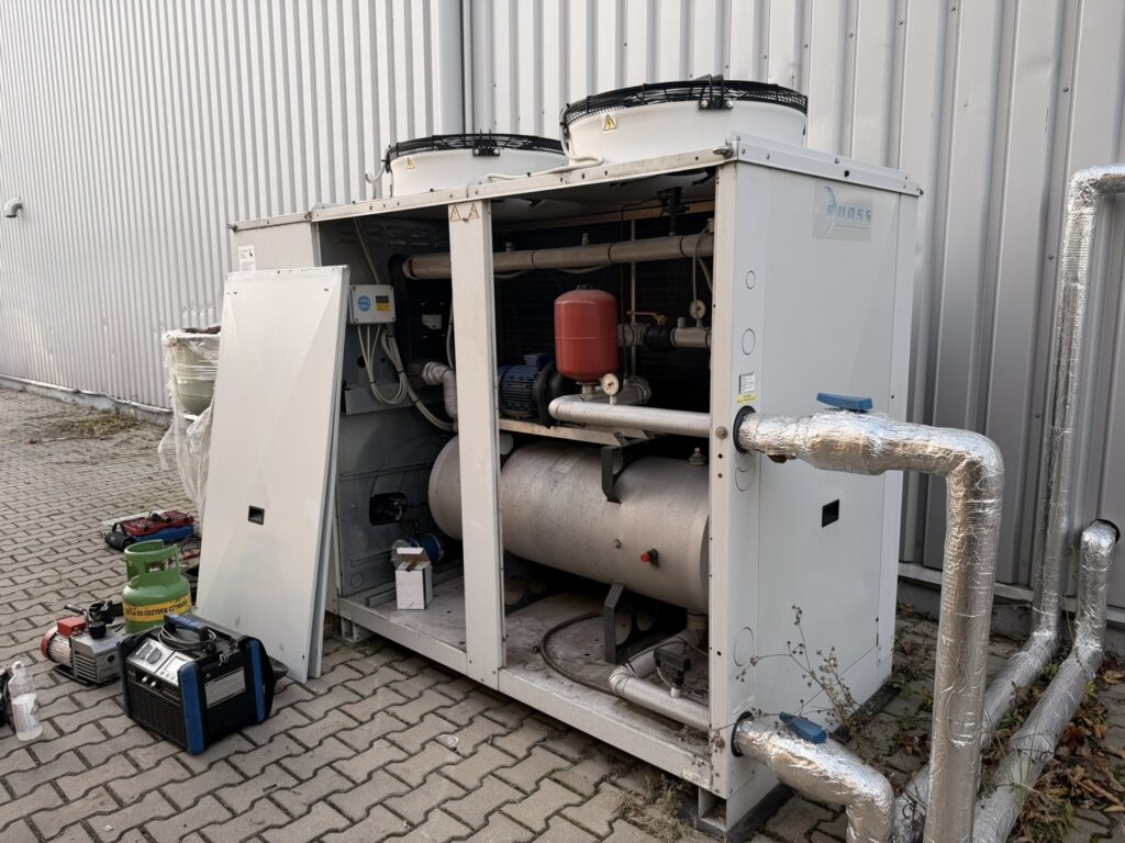
Install the tank in the return line when the aim is stable compressor operation, because it then smooths the temperature the chiller sees. Install it in the supply line when the aim is stable supply temperature at the consumers. A four-connection tank also works as a hydraulic separator between the chiller pump and the secondary circuit; in that case pay attention to the flow balance, so that warm return water does not mix into the supply.
Insulate the tank as well as the pipes, with a closed-cell material and a vapour barrier. A buffer tank at 7 °C in a warm plant room collects condensation within days if the insulation has a gap. Our dew point calculator shows when this happens. More about water side design is on the chilled water installations page.
Frequently asked questions
Does an inverter chiller need a buffer tank?
Often a smaller one, sometimes none. An inverter compressor can modulate down to 20 to 30 % before it stops, so the step that matters is small. Check the minimum volume in the manual, which also covers defrost and control stability.
Is the buffer tank volume the same as the minimum volume?
No. The minimum volume is the total water content needed. The buffer tank only has to add what the pipes, evaporator and consumers do not already hold.
What control band should I enter?
Use the difference between the compressor start and stop temperature in the controller. Typical values are 2 to 4 K. If you are not sure, read the setpoint and differential in the controller menu or enter 2 K to stay on the safe side.
Can a buffer tank be too big?
Technically a larger tank only makes the control slower and the start-up longer. The practical limits are cost, space, heat gain through the insulation and the time it takes to cool down the system after a stop.
Is your chiller short cycling?
We check the controls, the water volume and the hydraulics and propose a solution that stops the compressor wear.